99 Results
View results:
Sort by:

The ASCE 7-22 Standard [1], Sect. 12.9.1.6 specifies when P-delta effects should be considered when running a modal response spectrum analysis for seismic design. In the NBC 2020 [2], Sent. 4.1.8.3.8.c gives only a short requirement that sway effects due to the interaction of gravity loads with the deformed structure should be considered. Therefore, there may be situations where second-order effects, also known as P-delta, must be considered when carrying out a seismic analysis.

For the ultimate limit state design, EN 1998‑1, Sections 2.2.2 and 4.4.2.2 require a calculation considering the second‑order theory (P‑Δ effect). This effect may be neglected only if the interstory drift sensitivity coefficient θ is less than 0.1.

Creating a validation example for Computational Fluid Dynamics (CFD) is a critical step in ensuring the accuracy and reliability of simulation results. This process involves comparing the outcomes of CFD simulations with experimental or analytical data from real-world scenarios. The objective is to establish that the CFD model can faithfully replicate the physical phenomena it is intended to simulate. This guide outlines the essential steps in developing a validation example for CFD simulation, from selecting a suitable physical scenario to analyzing and comparing the results. By meticulously following these steps, engineers and researchers can enhance the credibility of their CFD models, paving the way for their effective application in diverse fields such as aerodynamics, aerospace, and environmental studies.

Wind direction plays a crucial role in shaping the outcomes of Computational Fluid Dynamics (CFD) simulations and the structural design of buildings and infrastructures. It is a determining factor in assessing how wind forces interact with structures, influencing the distribution of wind pressures, and consequently, the structural responses. Understanding the impact of wind direction is essential for developing designs that can withstand varying wind forces, ensuring the safety and durability of structures. Simplified, the wind direction helps in fine-tuning CFD simulations and guiding structural design principles for optimal performance and resilience against wind-induced effects.

When a concrete slab is set upon the top flange, its effect is like a lateral support (composite construction), preventing problems of torsional buckling stability. If there is a negative distribution of the bending moment, the bottom flange is subjected to compression and the top flange is under tension. If the lateral support given by the stiffness of the web is insufficient, the angle between the bottom flange and the web intersection line is variable in this case so that there is a possibility of distortional buckling for the bottom flange.

For the stability verification of members using the equivalent member method, it is necessary to define effective or lateral-torsional buckling lengths in order to determine a critical load for stability failure. In this article an RFEM 6-specific function is presented, by which you can assign an eccentricity to the nodal supports and thus influence the determination of the critical bending moment considered in the stability analysis.

The CSA S16:19 Stability Effects in Elastic Analysis method in Annex O.2 is an alternative option to the Simplified Stability Analysis Method in Clause 8.4.3. This article will describe the requirements of Annex O.2 and application in RFEM 6.

The Steel Joist Institute (SJI) previously developed Virtual Joist tables to estimate the section properties for Open Web Steel Joists. These Virtual Joist sections are characterized as equivalent wide-flange beams which closely approximate the joist chord area, effective moment of inertia, and weight. Virtual Joists are also available in the RFEM and RSTAB cross-section database.

The “Modal Analysis” add-on in RFEM 6 allows you to perform modal analysis of structural systems, thus determining natural vibration values such as natural frequencies, mode shapes, modal masses, and effective modal mass factors. These results can be used for vibration design, as well as for further dynamic analyses (for example, loading by a response spectrum).

Consideration of p-δ Second-Order Effects in RFEM 6 and RSTAB 9

Modal analysis is the starting point for the dynamic analysis of structural systems. You can use it to determine natural vibration values such as natural frequencies, mode shapes, modal masses, and effective modal mass factors. This outcome can be used for vibration design, and it can be used for further dynamic analyses (for example, loading by a response spectrum).

The AISC 360-16 steel standard requires stability consideration for a structure as a whole and each of its elements. Various methods for this are available, including direct consideration in the analysis, the effective length method, and the direct analysis method. This article will highlight the important requirements from Ch. C [1] and the direct analysis method to be incorporated in a structural steel model along with the application in RFEM 6.

Defining the appropriate effective length is crucial in obtaining the correct member design capacity. For X-bracing that is connected at the center, engineers often wonder if the full end-to-end length of the member shall be used, or whether using half of the length to where the members are connected is sufficient.This article outlines the recommendations given by the AISC and provides an example on how to specify the effective length of the X-braces in RFEM.

The effects due to snow load are described in the American standard ASCE/SEI 7-16 and in Eurocode 1, Parts 1 through 3. These standards are implemented in the new RFEM 6 program and the Snow Load Wizard, which serves to facilitate the application of snow loads. In addition to this, the most recent generation of the program allows the construction site to be specified on a digital map, thus allowing the snow load zone to be imported automatically. These data are, in turn, used by the Load Wizard to simulate the effects due to the snow load.

In accordance with Sect. 6.6.3.1.1 and Clause 10.14.1.2 of ACI 318-19 and CSA A23.3-19, respectively, RFEM effectively takes into consideration concrete member and surface stiffness reduction for various element types. Available selection types include cracked and uncracked walls, flat plates and slabs, beams, and columns. The multiplier factors available within the program are taken directly from Table 6.6.3.1.1(a) and Table 10.14.1.2.

Steel has poor thermal properties in terms of fire resistance. The thermal expansion for increasing temperature is very high compared to that of other building materials, and might result in effects that were not present in the design at normal temperature due to restraint in the component.As temperature increases, steel ductility increases, whereas its strength decreases. Since steel loses 50% of its strength at temperature of 600 °C, it is important to protect components against fire effects. In the case of protected steel components, the fire resistance duration can be increased due to the improved heating behavior.

The stability checks for the equivalent member design according to EN 1993-1-1, AISC 360, CSA S16, and other international standards require consideration of the design length (that is, the effective length of the members). In RFEM 6, it is possible to determine the effective length manually by assigning nodal supports and effective length factors or, on the other hand, by importing it from the stability analysis. Both options will be demonstrated in this article by determining the effective length of the framed column in Image 1.

Complex structures are assemblies of structural elements with various properties. However, certain elements can have the same properties in terms of supports, nonlinearities, end modifications, hinges, and so on, as well as design (for example, effective lengths, design supports, reinforcement, service classes, section reductions, and so on). In RFEM 6, these elements can be grouped on the basis of their shared properties and thus can be considered together for both modeling and design.

Building Model is one of the special solution add-ons in RFEM 6. It is an advantageous tool for modeling, with which building stories can be created and manipulated easily. Building Model can be activated at the beginning of the modeling process and afterwards.

In CRANEWAY, the action of a rail as "statically effective" or "statically ineffective" is defined under "Rail‑Flange Connection" in the Details dialog box. This setting controls the calculation of the load introduction length according to EN 1993-6, Tab. 5.1.

The RF-STABILITY add-on module determines any critical load factors, effective lengths, and eigenvectors of RFEM models. Stability analyses can be carried out by various eigenvalue methods, the advantages of which depend on the structural system as well as computer configurations.

The German Annex to EN 1992‑1‑1, the National Addition NCI to Article 9.2.1.2 (2), recommends to dispose the tension reinforcement in the flange plate of T‑beam cross‑sections on a maximum of one width corresponding to the half of a computed effective flange width beff,i according to Expression (5,7a).

Structure stability is not a new phenomenon when referring to steel design. The Canadian steel design standard CSA S16 and the most recent 2019 release are no exception. Detailed stability requirements can be addressed with either the Simplified Stability Analysis Method in Clause 8.4.3 or, new to the 2019 standard, the Stability Effects in Elastic Analysis method provided in Annex O.

In RF‑/STEEL EC3, you can assign the same input data to several members or sets of members at the same time. The simultaneous assignment of the input data is possible for intermediate supports, effective lengths, nodal supports, member end hinges, and shear panel and rotational restraint.
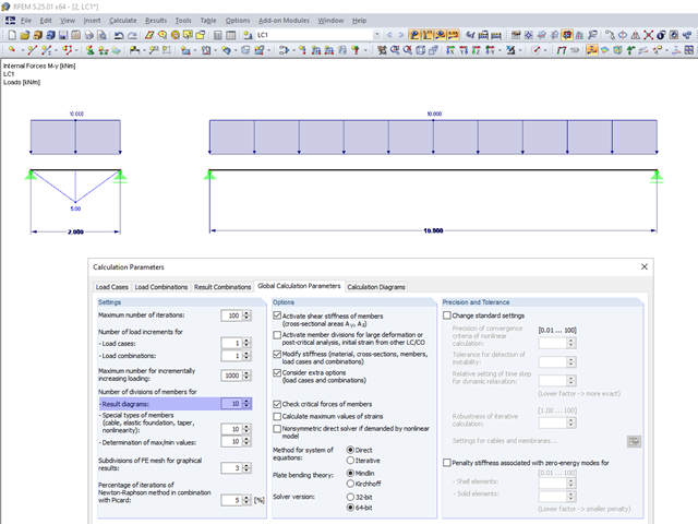
In the calculation parameters, you can set the number of member divisions for result diagrams. The effect of this setting option is shown in the following images.

If nonlinear effects - such as failing supports, foundations, member nonlinearities, or contact solids - are used in the model, you can deactivate them in the global calculation parameters.

In the RF-/FOUNDATION Pro add-on module, you can select the automatic dimensioning of the foundation plate geometry. In the dialog box for the design parameters of the foundation plate, you can, for example, specify the increment for the increase of the base area and the foundation plate thickness. You can also automatically increase the covering for a stabilizing effect of the geotechnical designs.

In the case of open cross-sections, the torsional load is removed mainly via secondary torsion, since the St. Venant torsional stiffness is low compared to the warping stiffness. Therefore, warping stiffeners in the cross-section are particularly interesting for the lateral-torsional buckling analysis, as they can significantly reduce the rotation. For this, end plates or welded stiffeners and sections are suitable.

The classification of cross-sections according to EN 1993-1-1 using Table 5.2 is a simple method for designing the local buckling of cross-section parts. For cross-sections of cross-section class 4, it is then necessary to determine the effective cross-section properties according to EN 1993-1-5 in order to consider the influence of local buckling in the ultimate limit state designs.
An effective way to represent reinforcement graphically is to arrange it in groups.